THE TUNING OF A DUPLEXER
A Saga of Suspense, Intrigue, Discovery, and Accomplishment
By John WBOCMC and Paul WBOGXD
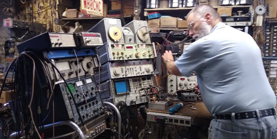
While troubleshooting a noise issue on the 146.82 SWIARC repeater it was determined that the duplexer needed to be serviced. John WBOCMC volunteered to look it over if it were transported to his workbench. Anxious to take advantage of this generous offer, the duplexer was removed from the 82 site and conveyed to John’s inner sanctum. You can see the duplexer set at the bottom center of photo ‘A’.
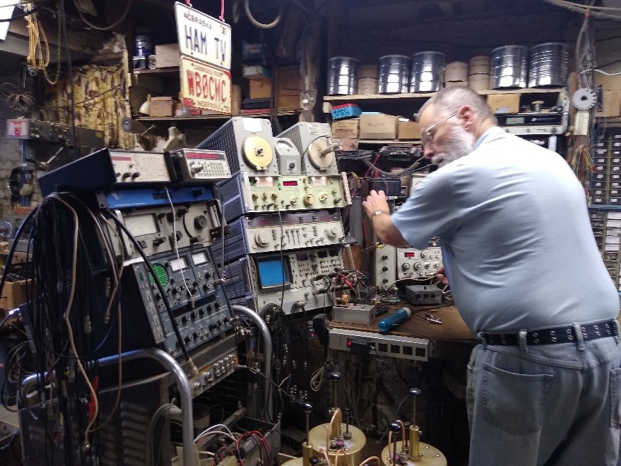
Photo ‘A’ – John WBOCMC at his workbench. SWIARC duplexer visible at bottom center of photo.
A word here about the type of duplexer we are working on for this article. It is a Band-Pass / Band-Reject style duplexer. It usually consists of two cavities in both the transmit and receive leg tuned to pass one frequency and notch, or reject, the other frequency. The transmit leg is tuned to pass the transmit frequency and notch the receive frequency; while the receive leg tuned to pass the receive frequency and reject the transmit frequency. Illustration ‘B’ is a spectrum analyzer display of a typical single cavity band pass / band reject filter. The “band pass” portion of the cavity is tuned to 155 MHz and shows approximately a 1 dB insertion loss. The “band reject” portion of the same cavity shows either a 27 or a 32 dB insertion loss, depending on which curve you are looking at.
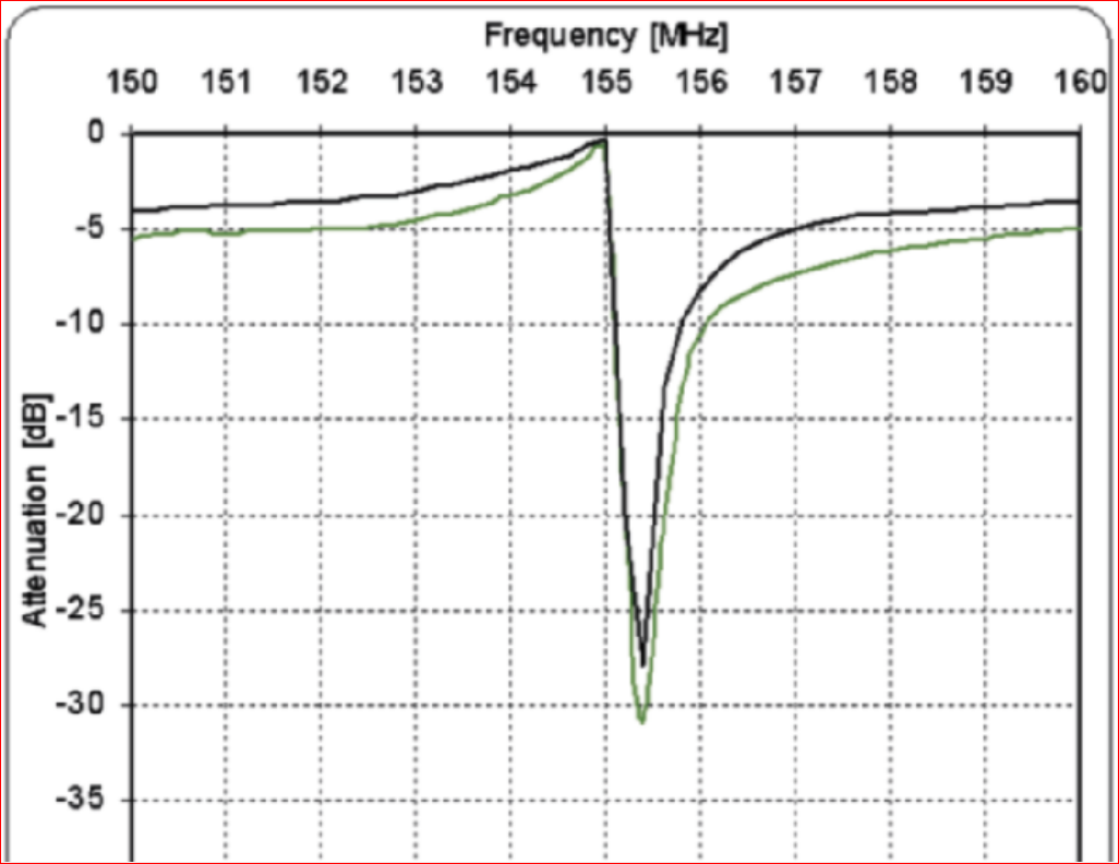
Illustration ‘B’ – A spectrum analyzer display of a typical single cavity band pass / band reject filter.
John went to work and set up his spectrum analyzer, sweep generator, and marker generator. After the test equipment was ready the duplexer receive leg (both cavities) was attached, with the sweep analyzer feeding into the receiver port and the sweep generator attached to the antenna port. Photo ‘C’ shows the curve of the SWIARC duplexer receive leg as it was when we started.
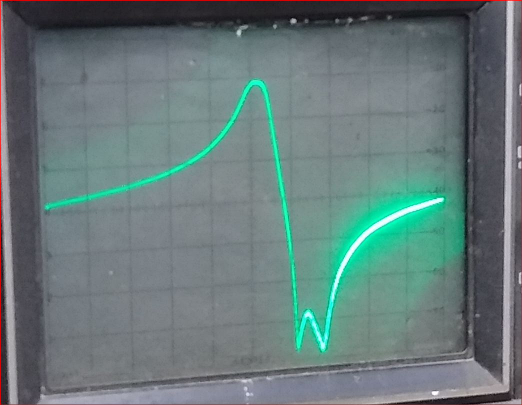
Photo ‘C’ shows the curve of the SWIARC duplexer receive leg as it was when we started.
Note the double notch on the right.
The peak on the left is the 146.22 receiver frequency that is passed through from the antenna port to the repeater receiver. The double notch on the right is supposed to be a single notch tuned to the 146.82 transmitter frequency. Each major graticule division is 10 dB, so the two notches are only about 66 dB down. The specification for this duplexer is 80 dB. The double notch occurs because the notch tuning on the two cavities don’t match. Each is notching at a slightly different frequency.
The test equipment was then connected to the duplexer with the generator attached to the transmit port and with the sweep analyzer attached to the antenna port. Photo ‘D’ shows the curve of the SWIARC duplexer transmit leg as it was when we started.
![]()
Photo ‘D’ shows the curve of the SWIARC duplexer transmit leg as it was when we started.
Note the abnormal notch on the left.
The little upward spike seen within the notch dip is the external marker generator used to mark the 146.22 MHz frequency within the display (labeled 146.22 MARKER in the photo). Again, you can see the double notch where the two duplexer cavities’ notch filters are not tuned to the same frequency. In fact, neither of the two notches are on the 146.22 frequency. 146.22 MHz is only about -55 dB instead of the -80 dB spec.
At this point, the duplexer was re-tuned to factory specifications or better. The transmit leg measured about 1.2 dB insertion loss on 146.82 MHz with a notch of –85 dB of rejection on 146.22 MHz. The receive leg measured about 1.4 dB insertion loss on 146.22 MHz with a notch of –83 dB of rejection on 146.82 MHz.
The SWIARC Yaesu Vertex RF deck was attached to the duplexer’s transmit and receive ports, and the antenna port was attached to a dummy load. Wattmeter readings showed about six watts out of the vertex into the duplexer, and about 4 watts out of the duplexer to the dummy load. No discernable desense could be detected.
Suddenly, with no apparent provocation, the wattmeter dropped from 4 to 0.5 watts and the spectrum analyzer showed a large amount of broadband RF noise across to width of the display. After about 30 seconds the noise cleared and the power output returned to normal. This is not a good development. This indicates some type of intermittent problem, and it needed to be resolved.
With the transmitter keyed up and all was working fine, we began wiggling cables, tapping on the various parts of the duplexer and in general trying to get the problem to reappear. Try as we might, we couldn’t get the problem to surface again. As we sat in suspense, discussing the situation, suddenly the problem returned. Again, we wiggled cables, tapped on the various parts of the duplexer and in general tried to get the problem to clear. No luck. Hmmm… Intriguing…
While the problem was still present, we started chasing the transmitter power loss through the system. This was accomplished by starting at the receiver port. Disconnecting the receiver at the duplexer had no effect, the problem remained. Re-attaching the receiver to the duplexer and disconnecting the cable connecting one cavity to the next also had no effect. This process continued until the receive leg was cleared. Then we started on the transmit leg, moving the wattmeter from the antenna port directly to each cavity in the transmit leg. While this was being completed the problem cleared.
While we were still intrigued as to what was causing the problem, we knew it was definitely in the duplexer cavities in the transmit leg. The next step was to check the insertion loops for the cavities. This is the part of each cavity where the signal is inserted into the cavity, and is where the cables attach to the cavity. Messing with the insertion loops is not for the faint at heart and should not be attempted unless necessary.
When the first insertion loop was removed and inspected under magnification it was discovered that the capacitor across the terminals was positioned extremely close to the metal strap. The capacitor being discussed is the ‘Z’ shaped component with the gray plastic material separating the metal plates. The bottom of that component is positioned with no discernable clearance to the naked eye. It is so close that a piece of paper wouldn’t fit in between them. See photo ‘E’.
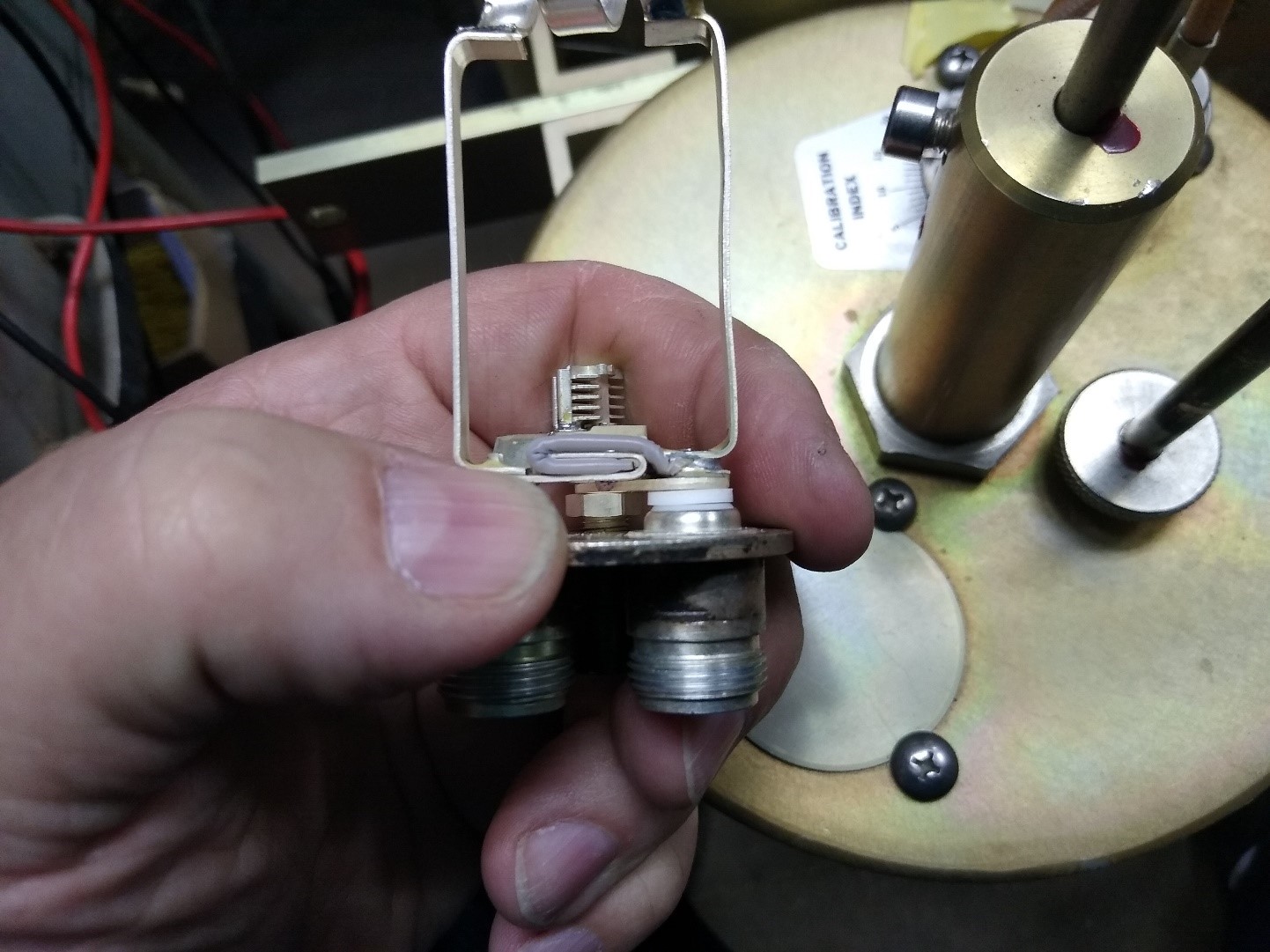
Photo ‘E’ – This photo shows the insertion loop with the Z-shaped capacitor almost touching the strap.
No space between them can be seen. The small trimming capacitor behind it is the notch adjustment.
Some minor physical tweaking increased the space from the bottom of the capacitor to approximately 1/32”. There was also an extremely small solder splash inside the loop that was removed. Photo ‘F’ shows one of these insertion loops after it has been adjusted. The space between the bottom of the capacitor and the strap can now clearly be seen. The insertion loop was then re-installed into the cavity.
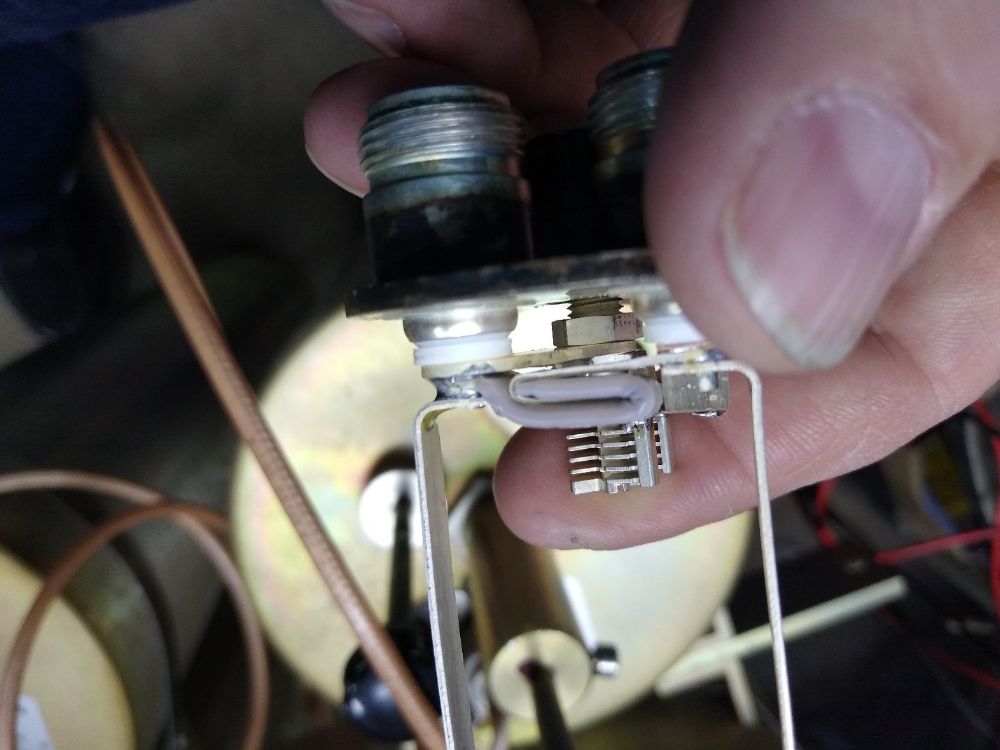
Photo ‘F’ – The space between the bottom of the ‘Z’ shaped capacitor and the strap can now clearly be seen
The insertion loop for the next cavity in that leg was next. After it was removed and inspected, the same problem was evident. The ‘Z’ shaped capacitor on the second insertion loop was also extremely close to the metal strap. The same physical adjustment was made to this second insertion loop and it was then re-installed into its cavity.
After the duplexer connections were all made ‘normal’, the duplexer was again connected to the sweep generator and spectrum analyzer. The tuning process as described at the beginning of this article was repeated, both for the transmit and receive legs of the duplexer. Again, factory specs were achieved.
After re-tuning, the Yaesu Vertex RF deck was again attached to the duplexer’s transmit and receive ports, and the dummy load attached to the antenna port. Extensive testing began, including wiggling cables, tapping on the various parts of the duplexer and in general trying to get the problem to reappear. The problem never returned. The wattmeter held steady at its approximately 4 watts output with no desense.
After discovering a problem that had been present since its manufacture at the factory, we had accomplished repairs and were able to return the duplexer to service on the SWIARC 146.82 MHz repeater the same day, confident that there is no problem with it.
For those who have always wondered what the inside of one of these cavities looks like, photo ‘G’ below is a view of the inside of a cavity that was visible with the insertion loop removed. There is a shorter tuning rod the is not visible in this photo as its view is blocked by the large tuning rod seen here.
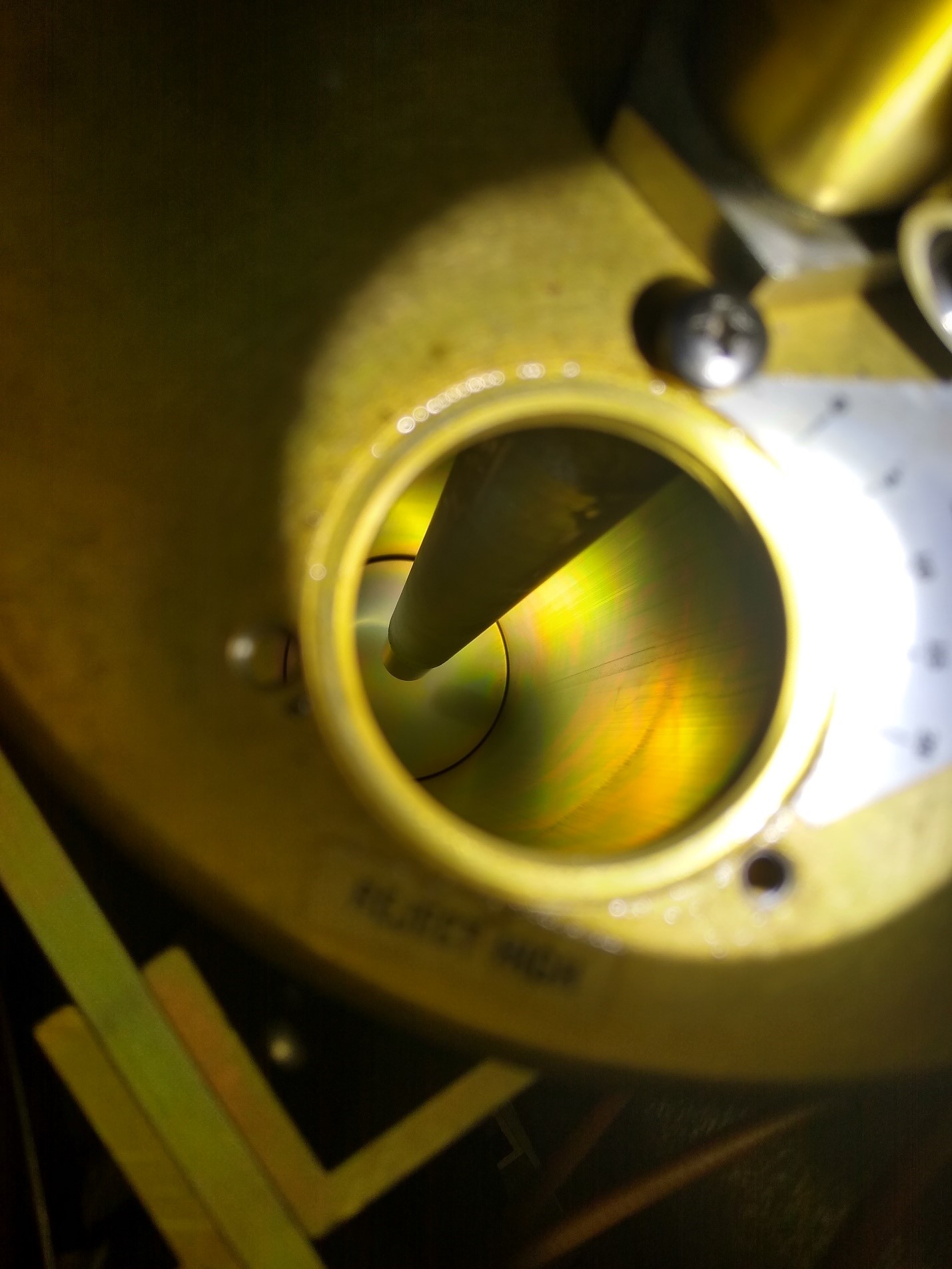
Photo ‘G’ – An inside view of a 2 meter cavity.